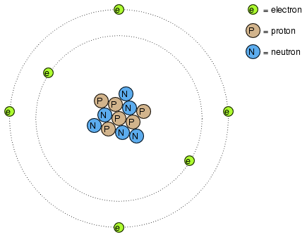
Total Pageviews

Pages

Friday, September 24, 2010

Voltage and current in a practical circuit

Because it takes energy to force electrons to flow against the opposition of a resistance, there will be voltage manifested (or "dropped") between any points in a circuit with resistance between them. It is important to note that although the amount of current (the quantity of electrons moving past a given point every second) is uniform in a simple circuit, the amount of voltage (potential energy per unit charge) between different sets of points in a single circuit may vary considerably:

Take this circuit as an example. If we label four points in this circuit with the numbers 1, 2, 3, and 4, we will find that the amount of current conducted through the wire between points 1 and 2 is exactly the same as the amount of current conducted through the lamp (between points 2 and 3). This same quantity of current passes through the wire between points 3 and 4, and through the battery (between points 1 and 4).

However, we will find the voltage appearing between any two of these points to be directly proportional to the resistance within the conductive path between those two points, given that the amount of current along any part of the circuit's path is the same (which, for this simple circuit, it is). In a normal lamp circuit, the resistance of a lamp will be much greater than the resistance of the connecting wires, so we should expect to see a substantial amount of voltage between points 2 and 3, with very little between points 1 and 2, or between 3 and 4. The voltage between points 1 and 4, of course, will be the full amount of "force" offered by the battery, which will be only slightly greater than the voltage across the lamp (between points 2 and 3).

This, again, is analogous to the water reservoir system:

Between points 2 and 3, where the falling water is releasing energy at the water-wheel, there is a difference of pressure between the two points, reflecting the opposition to the flow of water through the water-wheel. From point 1 to point 2, or from point 3 to point 4, where water is flowing freely through reservoirs with little opposition, there is little or no difference of pressure (no potential energy). However, the rate of water flow in this continuous system is the same everywhere (assuming the water levels in both pond and reservoir are unchanging): through the pump, through the water-wheel, and through all the pipes. So it is with simple electric circuits: the rate of electron flow is the same at every point in the circuit, although voltages may differ between different sets of points.

Resistance

The circuit in the previous section is not a very practical one. In fact, it can be quite dangerous to build (directly connecting the poles of a voltage source together with a single piece of wire). The reason it is dangerous is because the magnitude of electric current may be very large in such a short circuit, and the release of energy very dramatic (usually in the form of heat). Usually, electric circuits are constructed in such a way as to make practical use of that released energy, in as safe a manner as possible.

One practical and popular use of electric current is for the operation of electric lighting. The simplest form of electric lamp is a tiny metal "filament" inside of a clear glass bulb, which glows white-hot ("incandesces") with heat energy when sufficient electric current passes through it. Like the battery, it has two conductive connection points, one for electrons to enter and the other for electrons to exit.

Connected to a source of voltage, an electric lamp circuit looks something like this:

As the electrons work their way through the thin metal filament of the lamp, they encounter more opposition to motion than they typically would in a thick piece of wire. This opposition to electric current depends on the type of material, its cross-sectional area, and its temperature. It is technically known as resistance. (It can be said that conductors have low resistance and insulators have very high resistance.) This resistance serves to limit the amount of current through the circuit with a given amount of voltage supplied by the battery, as compared with the "short circuit" where we had nothing but a wire joining one end of the voltage source (battery) to the other.

When electrons move against the opposition of resistance, "friction" is generated. Just like mechanical friction, the friction produced by electrons flowing against a resistance manifests itself in the form of heat. The concentrated resistance of a lamp's filament results in a relatively large amount of heat energy dissipated at that filament. This heat energy is enough to cause the filament to glow white-hot, producing light, whereas the wires connecting the lamp to the battery (which have much lower resistance) hardly even get warm while conducting the same amount of current.

As in the case of the short circuit, if the continuity of the circuit is broken at any point, electron flow stops throughout the entire circuit. With a lamp in place, this means that it will stop glowing:

As before, with no flow of electrons, the entire potential (voltage) of the battery is available across the break, waiting for the opportunity of a connection to bridge across that break and permit electron flow again. This condition is known as an open circuit, where a break in the continuity of the circuit prevents current throughout. All it takes is a single break in continuity to "open" a circuit. Once any breaks have been connected once again and the continuity of the circuit re-established, it is known as a closed circuit.

What we see here is the basis for switching lamps on and off by remote switches. Because any break in a circuit's continuity results in current stopping throughout the entire circuit, we can use a device designed to intentionally break that continuity (called a switch), mounted at any convenient location that we can run wires to, to control the flow of electrons in the circuit:

This is how a switch mounted on the wall of a house can control a lamp that is mounted down a long hallway, or even in another room, far away from the switch. The switch itself is constructed of a pair of conductive contacts (usually made of some kind of metal) forced together by a mechanical lever actuator or pushbutton. When the contacts touch each other, electrons are able to flow from one to the other and the circuit's continuity is established; when the contacts are separated, electron flow from one to the other is prevented by the insulation of the air between, and the circuit's continuity is broken.

Perhaps the best kind of switch to show for illustration of the basic principle is the "knife" switch:

A knife switch is nothing more than a conductive lever, free to pivot on a hinge, coming into physical contact with one or more stationary contact points which are also conductive. The switch shown in the above illustration is constructed on a porcelain base (an excellent insulating material), using copper (an excellent conductor) for the "blade" and contact points. The handle is plastic to insulate the operator's hand from the conductive blade of the switch when opening or closing it.

Here is another type of knife switch, with two stationary contacts instead of one:

The particular knife switch shown here has one "blade" but two stationary contacts, meaning that it can make or break more than one circuit. For now this is not terribly important to be aware of, just the basic concept of what a switch is and how it works.

Knife switches are great for illustrating the basic principle of how a switch works, but they present distinct safety problems when used in high-power electric circuits. The exposed conductors in a knife switch make accidental contact with the circuit a distinct possibility, and any sparking that may occur between the moving blade and the stationary contact is free to ignite any nearby flammable materials. Most modern switch designs have their moving conductors and contact points sealed inside an insulating case in order to mitigate these hazards. A photograph of a few modern switch types show how the switching mechanisms are much more concealed than with the knife design:

In keeping with the "open" and "closed" terminology of circuits, a switch that is making contact from one connection terminal to the other (example: a knife switch with the blade fully touching the stationary contact point) provides continuity for electrons to flow through, and is called a closed switch. Conversely, a switch that is breaking continuity (example: a knife switch with the blade not touching the stationary contact point) won't allow electrons to pass through and is called an open switch. This terminology is often confusing to the new student of electronics, because the words "open" and "closed" are commonly understood in the context of a door, where "open" is equated with free passage and "closed" with blockage. With electrical switches, these terms have opposite meaning: "open" means no flow while "closed" means free passage of electrons.

  • REVIEW:
  • Resistance is the measure of opposition to electric current.
  • A short circuit is an electric circuit offering little or no resistance to the flow of electrons. Short circuits are dangerous with high voltage power sources because the high currents encountered can cause large amounts of heat energy to be released.
  • An open circuit is one where the continuity has been broken by an interruption in the path for electrons to flow.
  • A closed circuit is one that is complete, with good continuity throughout.
  • A device designed to open or close a circuit under controlled conditions is called a switch.
  • The terms "open" and "closed" refer to switches as well as entire circuits. An open switch is one without continuity: electrons cannot flow through it. A closed switch is one that provides a direct (low resistance) path for electrons to flow through.

Voltage and current

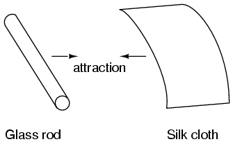
If we take the examples of wax and wool which have been rubbed together, we find that the surplus of electrons in the wax (negative charge) and the deficit of electrons in the wool (positive charge) creates an imbalance of charge between them. This imbalance manifests itself as an attractive force between the two objects:

If a conductive wire is placed between the charged wax and wool, electrons will flow through it, as some of the excess electrons in the wax rush through the wire to get back to the wool, filling the deficiency of electrons there:

The imbalance of electrons between the atoms in the wax and the atoms in the wool creates a force between the two materials. With no path for electrons to flow from the wax to the wool, all this force can do is attract the two objects together. Now that a conductor bridges the insulating gap, however, the force will provoke electrons to flow in a uniform direction through the wire, if only momentarily, until the charge in that area neutralizes and the force between the wax and wool diminishes.

The electric charge formed between these two materials by rubbing them together serves to store a certain amount of energy. This energy is not unlike the energy stored in a high reservoir of water that has been pumped from a lower-level pond:

The influence of gravity on the water in the reservoir creates a force that attempts to move the water down to the lower level again. If a suitable pipe is run from the reservoir back to the pond, water will flow under the influence of gravity down from the reservoir, through the pipe:

It takes energy to pump that water from the low-level pond to the high-level reservoir, and the movement of water through the piping back down to its original level constitutes a releasing of energy stored from previous pumping.

If the water is pumped to an even higher level, it will take even more energy to do so, thus more energy will be stored, and more energy released if the water is allowed to flow through a pipe back down again:

Electrons are not much different. If we rub wax and wool together, we "pump" electrons away from their normal "levels," creating a condition where a force exists between the wax and wool, as the electrons seek to re-establish their former positions (and balance within their respective atoms). The force attracting electrons back to their original positions around the positive nuclei of their atoms is analogous to the force gravity exerts on water in the reservoir, trying to draw it down to its former level.

Just as the pumping of water to a higher level results in energy being stored, "pumping" electrons to create an electric charge imbalance results in a certain amount of energy being stored in that imbalance. And, just as providing a way for water to flow back down from the heights of the reservoir results in a release of that stored energy, providing a way for electrons to flow back to their original "levels" results in a release of stored energy.

When the electrons are poised in that static condition (just like water sitting still, high in a reservoir), the energy stored there is called potential energy, because it has the possibility (potential) of release that has not been fully realized yet. When you scuff your rubber-soled shoes against a fabric carpet on a dry day, you create an imbalance of electric charge between yourself and the carpet. The action of scuffing your feet stores energy in the form of an imbalance of electrons forced from their original locations. This charge (static electricity) is stationary, and you won't realize that energy is being stored at all. However, once you place your hand against a metal doorknob (with lots of electron mobility to neutralize your electric charge), that stored energy will be released in the form of a sudden flow of electrons through your hand, and you will perceive it as an electric shock!

This potential energy, stored in the form of an electric charge imbalance and capable of provoking electrons to flow through a conductor, can be expressed as a term called voltage, which technically is a measure of potential energy per unit charge of electrons, or something a physicist would call specific potential energy. Defined in the context of static electricity, voltage is the measure of work required to move a unit charge from one location to another, against the force which tries to keep electric charges balanced. In the context of electrical power sources, voltage is the amount of potential energy available (work to be done) per unit charge, to move electrons through a conductor.

Because voltage is an expression of potential energy, representing the possibility or potential for energy release as the electrons move from one "level" to another, it is always referenced between two points. Consider the water reservoir analogy:

Because of the difference in the height of the drop, there's potential for much more energy to be released from the reservoir through the piping to location 2 than to location 1. The principle can be intuitively understood in dropping a rock: which results in a more violent impact, a rock dropped from a height of one foot, or the same rock dropped from a height of one mile? Obviously, the drop of greater height results in greater energy released (a more violent impact). We cannot assess the amount of stored energy in a water reservoir simply by measuring the volume of water any more than we can predict the severity of a falling rock's impact simply from knowing the weight of the rock: in both cases we must also consider how far these masses will drop from their initial height. The amount of energy released by allowing a mass to drop is relative to the distance between its starting and ending points. Likewise, the potential energy available for moving electrons from one point to another is relative to those two points. Therefore, voltage is always expressed as a quantity between two points. Interestingly enough, the analogy of a mass potentially "dropping" from one height to another is such an apt model that voltage between two points is sometimes called a voltage drop.

Voltage can be generated by means other than rubbing certain types of materials against each other. Chemical reactions, radiant energy, and the influence of magnetism on conductors are a few ways in which voltage may be produced. Respective examples of these three sources of voltage are batteries, solar cells, and generators (such as the "alternator" unit under the hood of your automobile). For now, we won't go into detail as to how each of these voltage sources works -- more important is that we understand how voltage sources can be applied to create electron flow in a circuit.

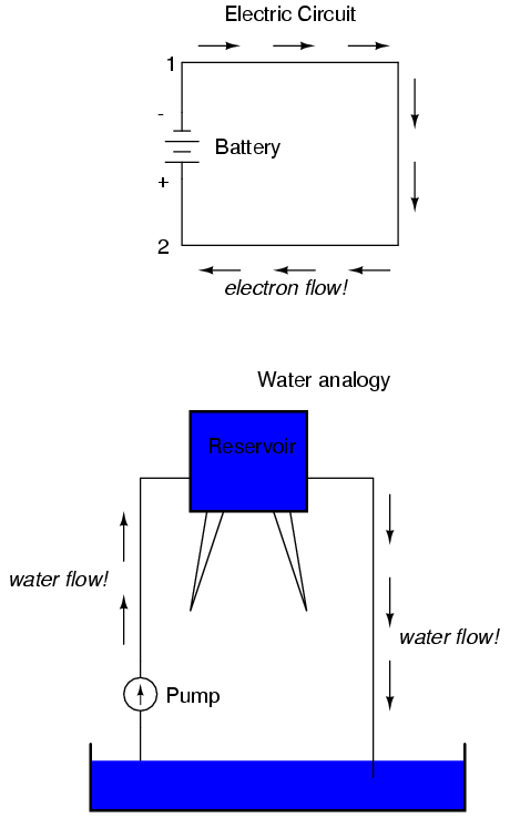
Let's take the symbol for a chemical battery and build a circuit step by step:

Any source of voltage, including batteries, have two points for electrical contact. In this case, we have point 1 and point 2 in the above diagram. The horizontal lines of varying length indicate that this is a battery, and they further indicate the direction which this battery's voltage will try to push electrons through a circuit. The fact that the horizontal lines in the battery symbol appear separated (and thus unable to serve as a path for electrons to move) is no cause for concern: in real life, those horizontal lines represent metallic plates immersed in a liquid or semi-solid material that not only conducts electrons, but also generates the voltage to push them along by interacting with the plates.

Notice the little "+" and "-" signs to the immediate left of the battery symbol. The negative (-) end of the battery is always the end with the shortest dash, and the positive (+) end of the battery is always the end with the longest dash. Since we have decided to call electrons "negatively" charged (thanks, Ben!), the negative end of a battery is that end which tries to push electrons out of it. Likewise, the positive end is that end which tries to attract electrons.

With the "+" and "-" ends of the battery not connected to anything, there will be voltage between those two points, but there will be no flow of electrons through the battery, because there is no continuous path for the electrons to move.

The same principle holds true for the water reservoir and pump analogy: without a return pipe back to the pond, stored energy in the reservoir cannot be released in the form of water flow. Once the reservoir is completely filled up, no flow can occur, no matter how much pressure the pump may generate. There needs to be a complete path (circuit) for water to flow from the pond, to the reservoir, and back to the pond in order for continuous flow to occur.

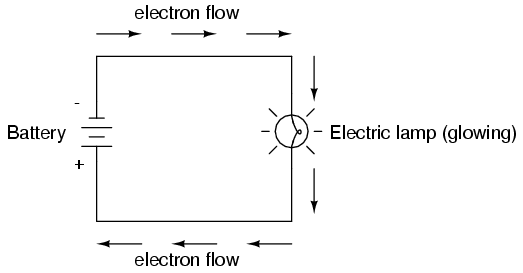
We can provide such a path for the battery by connecting a piece of wire from one end of the battery to the other. Forming a circuit with a loop of wire, we will initiate a continuous flow of electrons in a clockwise direction:

So long as the battery continues to produce voltage and the continuity of the electrical path isn't broken, electrons will continue to flow in the circuit. Following the metaphor of water moving through a pipe, this continuous, uniform flow of electrons through the circuit is called a current. So long as the voltage source keeps "pushing" in the same direction, the electron flow will continue to move in the same direction in the circuit. This single-direction flow of electrons is called a Direct Current, or DC. In the second volume of this book series, electric circuits are explored where the direction of current switches back and forth: Alternating Current, or AC. But for now, we'll just concern ourselves with DC circuits.

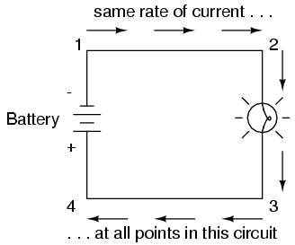
Because electric current is composed of individual electrons flowing in unison through a conductor by moving along and pushing on the electrons ahead, just like marbles through a tube or water through a pipe, the amount of flow throughout a single circuit will be the same at any point. If we were to monitor a cross-section of the wire in a single circuit, counting the electrons flowing by, we would notice the exact same quantity per unit of time as in any other part of the circuit, regardless of conductor length or conductor diameter.

If we break the circuit's continuity at any point, the electric current will cease in the entire loop, and the full voltage produced by the battery will be manifested across the break, between the wire ends that used to be connected:

Notice the "+" and "-" signs drawn at the ends of the break in the circuit, and how they correspond to the "+" and "-" signs next to the battery's terminals. These markers indicate the direction that the voltage attempts to push electron flow, that potential direction commonly referred to as polarity. Remember that voltage is always relative between two points. Because of this fact, the polarity of a voltage drop is also relative between two points: whether a point in a circuit gets labeled with a "+" or a "-" depends on the other point to which it is referenced. Take a look at the following circuit, where each corner of the loop is marked with a number for reference:

With the circuit's continuity broken between points 2 and 3, the polarity of the voltage dropped between points 2 and 3 is "-" for point 2 and "+" for point 3. The battery's polarity (1 "-" and 4 "+") is trying to push electrons through the loop clockwise from 1 to 2 to 3 to 4 and back to 1 again.

Now let's see what happens if we connect points 2 and 3 back together again, but place a break in the circuit between points 3 and 4:

With the break between 3 and 4, the polarity of the voltage drop between those two points is "+" for 4 and "-" for 3. Take special note of the fact that point 3's "sign" is opposite of that in the first example, where the break was between points 2 and 3 (where point 3 was labeled "+"). It is impossible for us to say that point 3 in this circuit will always be either "+" or "-", because polarity, like voltage itself, is not specific to a single point, but is always relative between two points!

  • REVIEW:
  • Electrons can be motivated to flow through a conductor by the same force manifested in static electricity.
  • Voltage is the measure of specific potential energy (potential energy per unit charge) between two locations. In layman's terms, it is the measure of "push" available to motivate electrons.
  • Voltage, as an expression of potential energy, is always relative between two locations, or points. Sometimes it is called a voltage "drop."
  • When a voltage source is connected to a circuit, the voltage will cause a uniform flow of electrons through that circuit called a current.
  • In a single (one loop) circuit, the amount of current at any point is the same as the amount of current at any other point.
  • If a circuit containing a voltage source is broken, the full voltage of that source will appear across the points of the break.
  • The +/- orientation of a voltage drop is called the polarity. It is also relative between two points.

Electric circuits

You might have been wondering how electrons can continuously flow in a uniform direction through wires without the benefit of these hypothetical electron Sources and Destinations. In order for the Source-and-Destination scheme to work, both would have to have an infinite capacity for electrons in order to sustain a continuous flow! Using the marble-and-tube analogy, the marble source and marble destination buckets would have to be infinitely large to contain enough marble capacity for a "flow" of marbles to be sustained.

The answer to this paradox is found in the concept of a circuit: a never-ending looped pathway for electrons. If we take a wire, or many wires joined end-to-end, and loop it around so that it forms a continuous pathway, we have the means to support a uniform flow of electrons without having to resort to infinite Sources and Destinations:

Each electron advancing clockwise in this circuit pushes on the one in front of it, which pushes on the one in front of it, and so on, and so on, just like a hula-hoop filled with marbles. Now, we have the capability of supporting a continuous flow of electrons indefinitely without the need for infinite electron supplies and dumps. All we need to maintain this flow is a continuous means of motivation for those electrons, which we'll address in the next section of this chapter.

It must be realized that continuity is just as important in a circuit as it is in a straight piece of wire. Just as in the example with the straight piece of wire between the electron Source and Destination, any break in this circuit will prevent electrons from flowing through it:

An important principle to realize here is that it doesn't matter where the break occurs. Any discontinuity in the circuit will prevent electron flow throughout the entire circuit. Unless there is a continuous, unbroken loop of conductive material for electrons to flow through, a sustained flow simply cannot be maintained.

  • REVIEW:
  • A circuit is an unbroken loop of conductive material that allows electrons to flow through continuously without beginning or end.
  • If a circuit is "broken," that means its conductive elements no longer form a complete path, and continuous electron flow cannot occur in it.
  • The location of a break in a circuit is irrelevant to its inability to sustain continuous electron flow. Any break, anywhere in a circuit prevents electron flow throughout the circuit.

Conductors, insulators, and electron flow

The electrons of different types of atoms have different degrees of freedom to move around. With some types of materials, such as metals, the outermost electrons in the atoms are so loosely bound that they chaotically move in the space between the atoms of that material by nothing more than the influence of room-temperature heat energy. Because these virtually unbound electrons are free to leave their respective atoms and float around in the space between adjacent atoms, they are often called free electrons.

In other types of materials such as glass, the atoms' electrons have very little freedom to move around. While external forces such as physical rubbing can force some of these electrons to leave their respective atoms and transfer to the atoms of another material, they do not move between atoms within that material very easily.

This relative mobility of electrons within a material is known as electric conductivity. Conductivity is determined by the types of atoms in a material (the number of protons in each atom's nucleus, determining its chemical identity) and how the atoms are linked together with one another. Materials with high electron mobility (many free electrons) are called conductors, while materials with low electron mobility (few or no free electrons) are called insulators.

Here are a few common examples of conductors and insulators:


  • Conductors:
  • silver
  • copper
  • gold
  • aluminum
  • iron
  • steel
  • brass
  • bronze
  • mercury
  • graphite
  • dirty water
  • concrete

  • Insulators:
  • glass
  • rubber
  • oil
  • asphalt
  • fiberglass
  • porcelain
  • ceramic
  • quartz
  • (dry) cotton
  • (dry) paper
  • (dry) wood
  • plastic
  • air
  • diamond
  • pure water

It must be understood that not all conductive materials have the same level of conductivity, and not all insulators are equally resistant to electron motion. Electrical conductivity is analogous to the transparency of certain materials to light: materials that easily "conduct" light are called "transparent," while those that don't are called "opaque." However, not all transparent materials are equally conductive to light. Window glass is better than most plastics, and certainly better than "clear" fiberglass. So it is with electrical conductors, some being better than others.

For instance, silver is the best conductor in the "conductors" list, offering easier passage for electrons than any other material cited. Dirty water and concrete are also listed as conductors, but these materials are substantially less conductive than any metal.

It should also be understood that some materials experience changes in their electrical properties under different conditions. Glass, for instance, is a very good insulator at room temperature, but becomes a conductor when heated to a very high temperature. Gases such as air, normally insulating materials, also become conductive if heated to very high temperatures. Most metals become poorer conductors when heated, and better conductors when cooled. Many conductive materials become perfectly conductive (this is called superconductivity) at extremely low temperatures.

While the normal motion of "free" electrons in a conductor is random, with no particular direction or speed, electrons can be influenced to move in a coordinated fashion through a conductive material. This uniform motion of electrons is what we call electricity, or electric current. To be more precise, it could be called dynamic electricity in contrast to static electricity, which is an unmoving accumulation of electric charge. Just like water flowing through the emptiness of a pipe, electrons are able to move within the empty space within and between the atoms of a conductor. The conductor may appear to be solid to our eyes, but any material composed of atoms is mostly empty space! The liquid-flow analogy is so fitting that the motion of electrons through a conductor is often referred to as a "flow."

A noteworthy observation may be made here. As each electron moves uniformly through a conductor, it pushes on the one ahead of it, such that all the electrons move together as a group. The starting and stopping of electron flow through the length of a conductive path is virtually instantaneous from one end of a conductor to the other, even though the motion of each electron may be very slow. An approximate analogy is that of a tube filled end-to-end with marbles:

The tube is full of marbles, just as a conductor is full of free electrons ready to be moved by an outside influence. If a single marble is suddenly inserted into this full tube on the left-hand side, another marble will immediately try to exit the tube on the right. Even though each marble only traveled a short distance, the transfer of motion through the tube is virtually instantaneous from the left end to the right end, no matter how long the tube is. With electricity, the overall effect from one end of a conductor to the other happens at the speed of light: a swift 186,000 miles per second!!! Each individual electron, though, travels through the conductor at a much slower pace.

If we want electrons to flow in a certain direction to a certain place, we must provide the proper path for them to move, just as a plumber must install piping to get water to flow where he or she wants it to flow. To facilitate this, wires are made of highly conductive metals such as copper or aluminum in a wide variety of sizes.

Remember that electrons can flow only when they have the opportunity to move in the space between the atoms of a material. This means that there can be electric current only where there exists a continuous path of conductive material providing a conduit for electrons to travel through. In the marble analogy, marbles can flow into the left-hand side of the tube (and, consequently, through the tube) if and only if the tube is open on the right-hand side for marbles to flow out. If the tube is blocked on the right-hand side, the marbles will just "pile up" inside the tube, and marble "flow" will not occur. The same holds true for electric current: the continuous flow of electrons requires there be an unbroken path to permit that flow. Let's look at a diagram to illustrate how this works:

A thin, solid line (as shown above) is the conventional symbol for a continuous piece of wire. Since the wire is made of a conductive material, such as copper, its constituent atoms have many free electrons which can easily move through the wire. However, there will never be a continuous or uniform flow of electrons within this wire unless they have a place to come from and a place to go. Let's add an hypothetical electron "Source" and "Destination:"

Now, with the Electron Source pushing new electrons into the wire on the left-hand side, electron flow through the wire can occur (as indicated by the arrows pointing from left to right). However, the flow will be interrupted if the conductive path formed by the wire is broken:

Since air is an insulating material, and an air gap separates the two pieces of wire, the once-continuous path has now been broken, and electrons cannot flow from Source to Destination. This is like cutting a water pipe in two and capping off the broken ends of the pipe: water can't flow if there's no exit out of the pipe. In electrical terms, we had a condition of electrical continuity when the wire was in one piece, and now that continuity is broken with the wire cut and separated.

If we were to take another piece of wire leading to the Destination and simply make physical contact with the wire leading to the Source, we would once again have a continuous path for electrons to flow. The two dots in the diagram indicate physical (metal-to-metal) contact between the wire pieces:

Now, we have continuity from the Source, to the newly-made connection, down, to the right, and up to the Destination. This is analogous to putting a "tee" fitting in one of the capped-off pipes and directing water through a new segment of pipe to its destination. Please take note that the broken segment of wire on the right hand side has no electrons flowing through it, because it is no longer part of a complete path from Source to Destination.

It is interesting to note that no "wear" occurs within wires due to this electric current, unlike water-carrying pipes which are eventually corroded and worn by prolonged flows. Electrons do encounter some degree of friction as they move, however, and this friction can generate heat in a conductor. This is a topic we'll explore in much greater detail later.

  • REVIEW:
  • In conductive materials, the outer electrons in each atom can easily come or go, and are called free electrons.
  • In insulating materials, the outer electrons are not so free to move.
  • All metals are electrically conductive.
  • Dynamic electricity, or electric current, is the uniform motion of electrons through a conductor.
  • Static electricity is an unmoving (if on an insulator), accumulated charge formed by either an excess or deficiency of electrons in an object. It is typically formed by charge separation by contact and separation of dissimilar materials.
  • For electrons to flow continuously (indefinitely) through a conductor, there must be a complete, unbroken path for them to move both into and out of that conductor.

Chapter 1: BASIC CONCEPTS OF ELECTRICITY

Static electricity

It was discovered centuries ago that certain types of materials would mysteriously attract one another after being rubbed together. For example: after rubbing a piece of silk against a piece of glass, the silk and glass would tend to stick together. Indeed, there was an attractive force that could be demonstrated even when the two materials were separated:

Glass and silk aren't the only materials known to behave like this. Anyone who has ever brushed up against a latex balloon only to find that it tries to stick to them has experienced this same phenomenon. Paraffin wax and wool cloth are another pair of materials early experimenters recognized as manifesting attractive forces after being rubbed together:

This phenomenon became even more interesting when it was discovered that identical materials, after having been rubbed with their respective cloths, always repelled each other:

It was also noted that when a piece of glass rubbed with silk was exposed to a piece of wax rubbed with wool, the two materials would attract one another:

Furthermore, it was found that any material demonstrating properties of attraction or repulsion after being rubbed could be classed into one of two distinct categories: attracted to glass and repelled by wax, or repelled by glass and attracted to wax. It was either one or the other: there were no materials found that would be attracted to or repelled by both glass and wax, or that reacted to one without reacting to the other.

More attention was directed toward the pieces of cloth used to do the rubbing. It was discovered that after rubbing two pieces of glass with two pieces of silk cloth, not only did the glass pieces repel each other, but so did the cloths. The same phenomenon held for the pieces of wool used to rub the wax:

Now, this was really strange to witness. After all, none of these objects were visibly altered by the rubbing, yet they definitely behaved differently than before they were rubbed. Whatever change took place to make these materials attract or repel one another was invisible.

Some experimenters speculated that invisible "fluids" were being transferred from one object to another during the process of rubbing, and that these "fluids" were able to effect a physical force over a distance. Charles Dufay was one the early experimenters who demonstrated that there were definitely two different types of changes wrought by rubbing certain pairs of objects together. The fact that there was more than one type of change manifested in these materials was evident by the fact that there were two types of forces produced: attraction and repulsion. The hypothetical fluid transfer became known as a charge.

One pioneering researcher, Benjamin Franklin, came to the conclusion that there was only one fluid exchanged between rubbed objects, and that the two different "charges" were nothing more than either an excess or a deficiency of that one fluid. After experimenting with wax and wool, Franklin suggested that the coarse wool removed some of this invisible fluid from the smooth wax, causing an excess of fluid on the wool and a deficiency of fluid on the wax. The resulting disparity in fluid content between the wool and wax would then cause an attractive force, as the fluid tried to regain its former balance between the two materials.

Postulating the existence of a single "fluid" that was either gained or lost through rubbing accounted best for the observed behavior: that all these materials fell neatly into one of two categories when rubbed, and most importantly, that the two active materials rubbed against each other always fell into opposing categories as evidenced by their invariable attraction to one another. In other words, there was never a time where two materials rubbed against each other both became either positive or negative.

Following Franklin's speculation of the wool rubbing something off of the wax, the type of charge that was associated with rubbed wax became known as "negative" (because it was supposed to have a deficiency of fluid) while the type of charge associated with the rubbing wool became known as "positive" (because it was supposed to have an excess of fluid). Little did he know that his innocent conjecture would cause much confusion for students of electricity in the future!

Precise measurements of electrical charge were carried out by the French physicist Charles Coulomb in the 1780's using a device called a torsional balance measuring the force generated between two electrically charged objects. The results of Coulomb's work led to the development of a unit of electrical charge named in his honor, the coulomb. If two "point" objects (hypothetical objects having no appreciable surface area) were equally charged to a measure of 1 coulomb, and placed 1 meter (approximately 1 yard) apart, they would generate a force of about 9 billion newtons (approximately 2 billion pounds), either attracting or repelling depending on the types of charges involved. The operational definition of a coulomb as the unit of electrical charge (in terms of force generated between point charges) was found to be equal to an excess or deficiency of about 6,250,000,000,000,000,000 electrons. Or, stated in reverse terms, one electron has a charge of about 0.00000000000000000016 coulombs. Being that one electron is the smallest known carrier of electric charge, this last figure of charge for the electron is defined as the elementary charge.

It was discovered much later that this "fluid" was actually composed of extremely small bits of matter called electrons, so named in honor of the ancient Greek word for amber: another material exhibiting charged properties when rubbed with cloth. Experimentation has since revealed that all objects are composed of extremely small "building-blocks" known as atoms, and that these atoms are in turn composed of smaller components known as particles. The three fundamental particles comprising most atoms are called protons, neutrons and electrons. Whilst the majority of atoms have a combination of protons, neutrons, and electrons, not all atoms have neutrons; an example is the protium isotope (1H1) of hydrogen (Hydrogen-1) which is the lightest and most common form of hydrogen which only has one proton and one electron. Atoms are far too small to be seen, but if we could look at one, it might appear something like this:

Even though each atom in a piece of material tends to hold together as a unit, there's actually a lot of empty space between the electrons and the cluster of protons and neutrons residing in the middle.

This crude model is that of the element carbon, with six protons, six neutrons, and six electrons. In any atom, the protons and neutrons are very tightly bound together, which is an important quality. The tightly-bound clump of protons and neutrons in the center of the atom is called the nucleus, and the number of protons in an atom's nucleus determines its elemental identity: change the number of protons in an atom's nucleus, and you change the type of atom that it is. In fact, if you could remove three protons from the nucleus of an atom of lead, you will have achieved the old alchemists' dream of producing an atom of gold! The tight binding of protons in the nucleus is responsible for the stable identity of chemical elements, and the failure of alchemists to achieve their dream.

Neutrons are much less influential on the chemical character and identity of an atom than protons, although they are just as hard to add to or remove from the nucleus, being so tightly bound. If neutrons are added or gained, the atom will still retain the same chemical identity, but its mass will change slightly and it may acquire strange nuclear properties such as radioactivity.

However, electrons have significantly more freedom to move around in an atom than either protons or neutrons. In fact, they can be knocked out of their respective positions (even leaving the atom entirely!) by far less energy than what it takes to dislodge particles in the nucleus. If this happens, the atom still retains its chemical identity, but an important imbalance occurs. Electrons and protons are unique in the fact that they are attracted to one another over a distance. It is this attraction over distance which causes the attraction between rubbed objects, where electrons are moved away from their original atoms to reside around atoms of another object.

Electrons tend to repel other electrons over a distance, as do protons with other protons. The only reason protons bind together in the nucleus of an atom is because of a much stronger force called the strong nuclear force which has effect only under very short distances. Because of this attraction/repulsion behavior between individual particles, electrons and protons are said to have opposite electric charges. That is, each electron has a negative charge, and each proton a positive charge. In equal numbers within an atom, they counteract each other's presence so that the net charge within the atom is zero. This is why the picture of a carbon atom had six electrons: to balance out the electric charge of the six protons in the nucleus. If electrons leave or extra electrons arrive, the atom's net electric charge will be imbalanced, leaving the atom "charged" as a whole, causing it to interact with charged particles and other charged atoms nearby. Neutrons are neither attracted to or repelled by electrons, protons, or even other neutrons, and are consequently categorized as having no charge at all.

The process of electrons arriving or leaving is exactly what happens when certain combinations of materials are rubbed together: electrons from the atoms of one material are forced by the rubbing to leave their respective atoms and transfer over to the atoms of the other material. In other words, electrons comprise the "fluid" hypothesized by Benjamin Franklin.

The result of an imbalance of this "fluid" (electrons) between objects is called static electricity. It is called "static" because the displaced electrons tend to remain stationary after being moved from one insulating material to another. In the case of wax and wool, it was determined through further experimentation that electrons in the wool actually transferred to the atoms in the wax, which is exactly opposite of Franklin's conjecture! In honor of Franklin's designation of the wax's charge being "negative" and the wool's charge being "positive," electrons are said to have a "negative" charging influence. Thus, an object whose atoms have received a surplus of electrons is said to be negatively charged, while an object whose atoms are lacking electrons is said to be positively charged, as confusing as these designations may seem. By the time the true nature of electric "fluid" was discovered, Franklin's nomenclature of electric charge was too well established to be easily changed, and so it remains to this day.

Michael Faraday proved (1832) that static electricity was the same as that produced by a battery or a generator. Static electricity is, for the most part, a nuisance. Black powder and smokeless powder have graphite added to prevent ignition due to static electricity. It causes damage to sensitive semiconductor circuitry. While it is possible to produce motors powered by high voltage and low current characteristic of static electricity, this is not economic. The few practical applications of static electricity include xerographic printing, the electrostatic air filter, and the high voltage Van de Graaff generator.

  • REVIEW:
  • All materials are made up of tiny "building blocks" known as atoms.
  • All naturally occurring atoms contain particles called electrons, protons, and neutrons, with the exception of the protium isotope (1H1) of hydrogen.
  • Electrons have a negative (-) electric charge.
  • Protons have a positive (+) electric charge.
  • Neutrons have no electric charge.
  • Electrons can be dislodged from atoms much easier than protons or neutrons.
  • The number of protons in an atom's nucleus determines its identity as a unique element.

Thursday, September 23, 2010

ies electrical syllabus

PAPER 1 objective n conventional


1. EM Theory

Electric and magnetic fields. Gauss’s Law and Amperes Law. Fields in dielectrics, conductors and magnetic materials. Maxwell’s equations. Time varying fields. Plane-Wave propagating in dielectric and conducting media. Transmission lines.

2. Electrical Materials

Band Theory, Conductors, Semi-conductors and Insulators. Super-conductivity. Insulators for electrical and electronic applications. Magnetic materials. Ferro and ferri magnetism. Ceramics, Properties and applications. Hall effect and its applications. Special semi conductors.

3. Electrical Circuits

Circuits elements. Kirchoff’s Laws. Mesh and nodal analysis. Network Theorems and applications. Natural response and forced response. Transient response and steady state response for arbitrary inputs. Properties of networks in terms of poles and zeros. Transfer function. Resonant circuits. Threephase circuits. Two-port networks. Elements of two-element network synthesis.

4. Measurements and Instrumentation

Units and Standards. Error analysis, measurement of current, Voltage, power, Power-factor and energy. Indicating instruments. Measurement of resistance, inductance, Capacitance and frequency. Bridge measurements. Electronic measuring instruments. Digital Voltmeter and frequency counter. Transducers and their applications to the measurement of non-electrical quantities like temperature, pressure, flow-rate displacement, acceleration, noise level etc. Data acquisition systems. A/D and D/A converters.

5. CONTROL SYSTEMS.

Mathematical modelling of physical systems. Block diagrams and signal flow graphs and their reduction. Time domain and frequency domain analysis of linear dynamical system. Errors for different type of inputs and stability criteria for feedback systems. Stability analysis using Routh-Hurwitz array, Nyquist plot and Bode plot. Root locus and Nicols chart and the estimation of gain and phase margin. Basic concepts of compensator design. State variable matrix and its use in system modelling and design. Sampled data system and performance of such a system with the samples in the error channel. Stability of sampled data system. Elements of non-linear control analysis. Control system components, electromechanical, hydraulic, pneumatic components.

Saturday, January 30, 2010

microprocessors quest

1. What are the flags in 8086? 
- In 8086 Carry flag, Parity flag, Auxiliary carry flag, Zero flag, Overflow flag, Trace flag, Interrupt flag, Direction flag, and Sign flag. 

2. What are the various interrupts in 8086? 
- Maskable interrupts, Non-Maskable interrupts. 

3. What is meant by Maskable interrupts? 
- An interrupt that can be turned off by the programmer is known as Maskable interrupt. 

4. What is Non-Maskable interrupts? 
- An interrupt which can be never be turned off (ie.disabled) is known as Non-Maskable interrupt. 

5. Which interrupts are generally used for critical events? 
- Non-Maskable interrupts are used in critical events. Such as Power failure, Emergency, Shut off etc., 

6. Give examples for Maskable interrupts?
- RST 7.5, RST6.5, RST5.5 are Maskable interrupts 

7. Give example for Non-Maskable interrupts? 
- Trap is known as Non-Maskable interrupts, which is used in emergency condition. 

8. What is the Maximum clock frequency in 8086? 
- 5 Mhz is the Maximum clock frequency in 8086. 

9. What are the various segment registers in 8086? 
- Code, Data, Stack, Extra Segment registers in 8086. 

10. Which Stack is used in 8086? - FIFO (First In First Out) stack is used in 8086.In this type of Stack the first stored information is retrieved first. 

11. What are the address lines for the software interrupts? - 
RST 0 0000 H

RST1 0008 H

RST2 0010 H

RST3 0018 H

RST4 0020 H

RST5 0028 H

RST6 0030 H

RST7 0038 H

12. What is SIM and RIM instructions? 
- SIM is Set Interrupt Mask. Used to mask the hardware interrupts. RIM is Read Interrupt Mask. Used to check whether the interrupt is Masked or not. 

13. Which is the tool used to connect the user and the computer? 
- Interpreter is the tool used to connect the user and the tool. 

14. What is the position of the Stack Pointer after the PUSH instruction?
- The address line is 02 less than the earlier value. 

15. What is the position of the Stack Pointer after the POP instruction?
- The address line is 02 greater than the earlier value. 

16. Logic calculations are done in which type of registers? 
- Accumulator is the register in which Arithmetic and Logic calculations are done. 

17. What are the different functional units in 8086? 
- Bus Interface Unit and Execution unit, are the two different functional units in 8086. 

18. Give examples for Micro controller? 
- Z80, Intel MSC51 &96, Motorola are the best examples of Microcontroller. 

19. What is meant by cross-compiler? 
- A program runs on one machine and executes on another is called as cross-compiler. 

20. What are the address lines for the hardware interrupts? 


RST 7.5 003C H

RST 6.5 0034 H

RST 5.5 002C H

TRAP 0024 H

21. Which Segment is used to store interrupt and subroutine return address registers? - 
Stack Segment in segment register is used to store interrupt and subroutine return address registers. 

22. Which Flags can be set or reset by the programmer and also used to control the operation of the processor? 
- Trace Flag, Interrupt Flag, Direction Flag. 

23. What does EU do?
- Execution Unit receives program instruction codes and data from BIU, executes these instructions and store the result in general registers. 

24. Which microprocessor accepts the program written for 8086 without any changes? 
- 8088 is that processor. 

25. What is the difference between 8086 and 8088? 

- The BIU in 8088 is 8-bit data bus & 16- bit in 8086.Instruction queue is 4 byte long in 8088and 6 byte in 8086.

microprocessor 4 aptransco/ies n others

8086 microprocessor architecture

Memory
Program, data and stack memories occupy the same memory space. The total addressable memory size is 1MB KB.
As the most of the processor instructions use 16-bit pointers the processor can effectively address only 64 KB of memory. To access memory outside of 64 KB the CPU uses special segment registers to specify where the code, stack and data 64 KB segments are positioned within 1 MB of memory (see the “Registers” section below).

16-bit pointers and data are stored as:
address: low-order byte
address+1: high-order byte

32-bit addresses are stored in “segment: offset” format as:
address: low-order byte of segment
address+1: high-order byte of segment
address+2: low-order byte of offset
address+3: high-order byte of offset

Physical memory address pointed by segment: offset pair is calculated as:

Address = ( * 16) +

Program memory – program can be located anywhere in memory. Jump and call instructions can be used for short jumps within currently selected 64 KB code segment, as well as for far jumps anywhere within 1 MB of memory. All conditional jump instructions can be used to jump within approximately +127 – -127 bytes from current instruction.

Data memory – the processor can access data in any one out of 4 available segments, which limits the size of accessible memory to 256 KB (if all four segments point to different 64 KB blocks). Accessing data from the Data, Code, Stack or Extra segments can be usually done by prefixing instructions with the DS:, CS:, SS: or ES: (some registers and instructions by default may use the ES or SS segments instead of DS segment).


Word data can be located at odd or even byte boundaries. The processor uses two memory accesses to read 16-bit word located at odd byte boundaries. Reading word data from even byte boundaries requires only one memory access.

Stack memory can be placed anywhere in memory. The stack can be located at odd memory addresses, but it is not recommended for performance reasons (see “Data Memory” above).

Reserved locations:
0000h – 03FFh are reserved for interrupt vectors. Each interrupt vector is a 32-bit pointer in format segment: offset.
FFFF0h – FFFFFh – after RESET the processor always starts program execution at the FFFF0h address.

Interrupts

The processor has the following interrupts:

INTR is a maskable hardware interrupt. The interrupt can be enabled/disabled using STI/CLI instructions or using more complicated method of updating the FLAGS register with the help of the POPF instruction. When an interrupt occurs, the processor stores FLAGS register into stack, disables further interrupts, fetches from the bus one byte representing interrupt type, and jumps to interrupt processing routine address of which is stored in location 4 * . Interrupt processing routine should return with the IRET instruction.

NMI is a non-maskable interrupt. Interrupt is processed in the same way as the INTR interrupt. Interrupt type of the NMI is 2, i.e. the address of the NMI processing routine is stored in location 0008h. This interrupt has higher priority then the maskable interrupt.

Software interrupts can be caused by:
INT instruction – breakpoint interrupt. This is a type 3 interrupt.
INT instruction – any one interrupt from available 256 interrupts.
INTO instruction – interrupt on overflow
Single-step interrupt – generated if the TF flag is set. This is a type 1 interrupt. When the CPU processes this interrupt it clears TF flag before calling the interrupt processing routine.
Processor exceptions: divide error (type 0), unused opcode (type 6) and escape opcode (type 7).

Software interrupt processing is the same as for the hardware interrupts.

I/O ports

65536 8-bit I/O ports: These ports can be also addressed as 32768 16-bit I/O ports.

Registers

Most of the registers contain data/instruction offsets within 64 KB memory segment. There are four different 64 KB segments for instructions, stack, data and extra data. To specify where in 1 MB of processor memory these 4 segments are located the processor uses four segment registers:

Code segment (CS) is a 16-bit register containing address of 64 KB segment with processor instructions. The processor uses CS segment for all accesses to instructions referenced by instruction pointer (IP) register. CS register cannot be changed directly. The CS register is automatically updated during far jump, far call and far return instructions.

Stack segment (SS) is a 16-bit register containing address of 64KB segment with program stack. By default, the processor assumes that all data referenced by the stack pointer (SP) and base pointer (BP) registers is located in the stack segment. SS register can be changed directly using POP instruction.

Data segment (DS) is a 16-bit register containing address of 64KB segment with program data. By default, the processor assumes that all data referenced by general registers (AX, BX, CX, DX) and index register (SI, DI) is located in the data segment. DS register can be changed directly using POP and LDS instructions.

Extra segment (ES) is a 16-bit register containing address of 64KB segment, usually with program data. By default, the processor assumes that the DI register references the ES segment in string manipulation instructions. ES register can be changed directly using POP and LES instructions.

It is possible to change default segments used by general and index registers by prefixing instructions with a CS, SS, DS or ES prefix.

All general registers of the 8086 microprocessor can be used for arithmetic and logic operations. The general registers are:

Accumulator register consists of 2 8-bit registers AL and AH, which can be combined together and used as a 16-bit register AX. AL in this case contains the low-order byte of the word, and AH contains the high-order byte. Accumulator can be used for I/O operations and string manipulation.

Base register consists of 2 8-bit registers BL and BH, which can be combined together and used as a 16-bit register BX. BL in this case contains the low-order byte of the word, and BH contains the high-order byte. BX register usually contains a data pointer used for based, based indexed or register indirect addressing.

Count register consists of 2 8-bit registers CL and CH, which can be combined together and used as a 16-bit register CX. When combined, CL register contains the low-order byte of the word, and CH contains the high-order byte. Count register can be used as a counter in string manipulation and shift/rotate instructions.

Data register consists of 2 8-bit registers DL and DH, which can be combined together and used as a 16-bit register DX. When combined, DL register contains the low-order byte of the word, and DH contains the high-order byte. Data register can be used as a port number in I/O operations. In integer 32-bit multiply and divide instruction the DX register contains high-order word of the initial or resulting number.

The following registers are both general and index registers:

Stack Pointer (SP) is a 16-bit register pointing to program stack.

Base Pointer (BP) is a 16-bit register pointing to data in stack segment. BP register is usually used for based, based indexed or register indirect addressing.

Source Index (SI) is a 16-bit register. SI is used for indexed, based indexed and register indirect addressing, as well as a source data address in string manipulation instructions.

Destination Index (DI) is a 16-bit register. DI is used for indexed, based indexed and register indirect addressing, as well as a destination data address in string manipulation instructions.

Other registers:

Instruction Pointer (IP) is a 16-bit register.

A flag is a 16-bit register containing 9 1-bit flags:
Overflow Flag (OF) – set if the result is too large positive number, or is too small negative number to fit into destination operand.
Direction Flag (DF) – if set then string manipulation instructions will auto-decrement index registers. If cleared then the index registers will be auto-incremented.
Interrupt-enable Flag (IF) – setting this bit enables maskable interrupts.
Single-step Flag (TF) – if set then single-step interrupt will occur after the next instruction.
Sign Flag (SF) – set if the most significant bit of the result is set.
Zero Flag (ZF) – set if the result is zero.
Auxiliary carry Flag (AF) – set if there was a carry from or borrow to bits 0-3 in the AL register.
Parity Flag (PF) – set if parity (the number of “1″ bits) in the low-order byte of the result is even.
Carry Flag (CF) – set if there was a carry from or borrow to the most significant bit during last result calculation.

Instruction Set

8086 instruction set consists of the following instructions:
Data moving instructions.
Arithmetic – add, subtract, increment, decrement, convert byte/word and compare.
Logic – AND, OR, exclusive OR, shift/rotate and test.
String manipulation – load, store, move, compare and scan for byte/word.
Control transfer – conditional, unconditional, call subroutine and return from subroutine.
Input/Output instructions.
Other – setting/clearing flag bits, stack operations, software interrupts, etc.

Addressing modes

Implied – the data value/data address is implicitly associated with the instruction.

Register – references the data in a register or in a register pair.

Immediate – the data is provided in the instruction.

Direct – the instruction operand specifies the memory address where data is located.

Register indirect – instruction specifies a register containing an address, where data is located. This addressing mode works with SI, DI, BX and BP registers.

Based – 8-bit or 16-bit instruction operand is added to the contents of a base register (BX or BP), the resulting value is a pointer to location where data resides.

Indexed – 8-bit or 16-bit instruction operand is added to the contents of an index register (SI or DI), the resulting value is a pointer to location where data resides.

Based Indexed – the contents of a base register (BX or BP) is added to the contents of an index register (SI or DI), the resulting value is a pointer to location where data resides.

Based Indexed with displacement – 8-bit or 16-bit instruction operand is added to the contents of a base register (BX or BP) and index register (SI or DI), the resulting value is a pointer to location where data resides.